Do we need to adjust the voltage control knob to change the motor speed? then this smart Motor PWM Speed Controller Circuit using IC 555 to control DC motor speed.
Also, it turn motor power ON and OFF very fast so motor gets average voltage and its speed changes; like dimmer switch but for motor.
Circuit Working:
Parts List:
| Components | Values | Quantity |
|---|---|---|
| Resistors | 470Ω, 1k 1/4 watt | 1 each |
| Potentiometer 5k | 1 | |
| Capacitors | Ceramic 1nF, 100nF | 1 each |
| Semiconductors | IC 555 | 1 |
| Transistor BD679 | 1 | |
| Diode 1N4004 | 1 | |
| Diode 1N4148 | 2 | |
| 6V Motor | 1 |
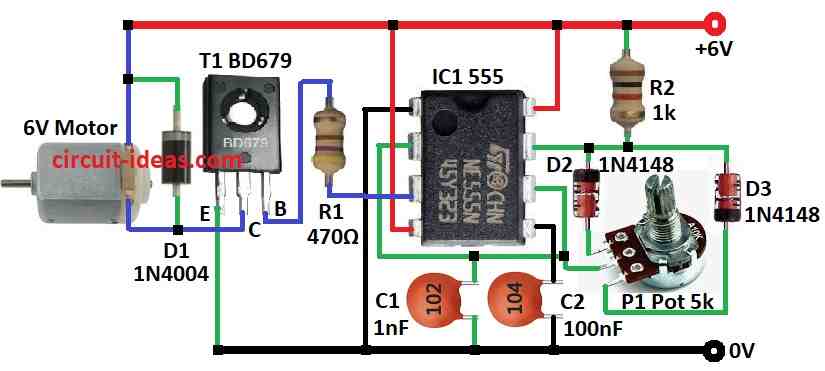
To begin with, 555 IC work as astable multivibrator and it makes square wave signal again and again; parts R1, C1 and P1 a knob set how fast signal comes.
Furthermore, changing P1 changes resistance so C1 charge/discharge time change and signal speed like frequency also changes.
Then this square wave goes to transistor BD679 and transistor act like switch which turn motor power ON/OFF fast.
Hence, the duty cycle refers to the amount of time the signal remains ON compared to the time it remains OFF; consequently, changing the duty cycle changes the average voltage supplied to the motor.
More ON time (high duty cycle) means motor run fast and less ON time (low duty cycle) means motor runs slow, so we can control speed using P1 knob and it changes duty cycle of 555 output so motor speed changes.
Lastly, diode D2 1N4148 protect 555 IC from voltage spikes when transistor turn OFF and diode D1 1N4004 stop back EMF from motor hurting the circuit.
Formulas:
To make PWM motor speed controller using 555 IC as astable multivibrator use this formula:
Frequency (f):
f = 1.44 / (R1 + 2 × R2) × C
where,
- R1 and R2 resistors connected to 555 IC
- C is timing capacitor
This formula gives how fast the square wave come like frequency.
Duty Cycle D:
D = R2 / (R1 + 2 × R2)
Duty cycle mean how long ON vs OFF is in one cycle, as more duty cycle means more motor speed and we can change duty cycle to control motor speed.
How to Build:
To build a Motor PWM Speed Controller Circuit using IC 555 follow the below mentioned steps for proper connections:
- First, pin 1 of IC 555 connects to ground
- Next, pin 2 connects to pin 6
- Then pin 3 connect to base of transistor T1 through resistor R1
- Now pin 4 connect to +6V supply and also pin 8 connects to +6V supply
- After that, pin 5 connect to ground using capacitor C and capacitor C2 also connect through pin 2 to ground
- Also, pin 6 connects to one leg of potentiometer P1
- Pin 7 connects to one end of diodes D2 & D3 and other ends of D2 & D3 goes to other 2 legs of P1
- Also, one side of resistor R2 connects to pin 7 and other side to +6V
- Then, connect the emitter of transistor T1 to ground and connect its collector to one side of the motor, and next, connect the base of T1 to pin 3 through resistor R1.
- Now one side of diode D1 connects to collector of T1 and other side between motor and +6V supply, also motor one side connects to collector of T1 and other side to +6V supply
Extra Notes:
- Motor speed depends on values of resistors and capacitor and we may need to change values based on our motor
- Also, choose transistor that can handle our motors current.
- Diode D1 protect circuit from back EMF which is very important
Conclusion:
To conclude, this simple low cost Motor PWM Speed Controller Circuit using IC 555 and transistor to control DC motor speed using PWM.
Moreover, it changes duty cycle which changes average voltage to motor and controls the speed.
Leave a Reply