Like in previous post on Automobile Engine Overheat Alert Circuit using LED, where driver gets indication through LED, but in this circuit, driver gets alert through sound and this sound comes from IC 555, which works as astable multivibrator and generates sound signal, also we can adjust temperature level for alarm using variable resistor which controls frequency of sound output.
Our car engine gets hot when cooling fails or when car runs long time, so high temperature can damage engine parts, therefore, we need a simple alarm system.
This Car Engine Heat Detector Circuit with Sound Alert gives warning sound when engine temperature becomes high, so it helps driver to take action and also, it helps car to get long life.
Moreover, this circuit is with low cost and easy to build.
Circuit Working:
Parts List:
| Components | Values | Quantity |
|---|---|---|
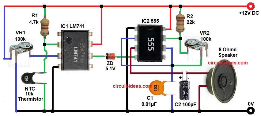
| Resistors | 4.7k, 22k 1/4 watts | 2 |
| Preset 100k | 2 | |
| Capacitors | Electrolytic 100µF 25V | 1 |
| Ceramic 0.01µF | 1 | |
| IC LM741, IC 555 Timer | 1 each | |
| Thermistor NTC 10k | 1 | |
| Zener Diode 5.1V | 1 | |
| Speaker 8 Ohms | 1 | |
| Power Supply +12V DC | 1 |
First, thermistor senses temperature and then this thermistor resistance changes with heat, when temperature increases, resistance decreases.
This thermistor works with R1 and VR1 to form voltage divider, output goes to IC1 LM741 comparator, and this comparator compares reference voltage and thermistor voltage.
When engine is cool the comparator output stays low, so no alarm.
When temperature crosses a set level, thermistor resistance drops and this changes voltage at comparator input, now comparator output becomes high.
This high output goes through Zener diode ZD1 and this Zener protects next stage from high voltage.
Then signal goes to IC2 555 timer which works in astable mode and generates square wave signal.
R2, VR2 and capacitor C1 decide frequency of oscillation.
Output of IC2 555 goes to speaker through capacitor C2 and speaker produces beep sound, through which the driver gets warning.
How to Build:
To build a Car Engine Heat Detector Circuit with Sound Alert follow the below connection steps:
- Start, the circuit by gathering all the parts as in circuit diagram above.
- Then start with IC1 with pin 2 inverting input connect to thermistor divider one end.
- Pin 3 non-inverting input connect to reference using VR1 center pin.
- Pin 4 V- connect directly to ground.
- Pin 6 output goes to Zener diode cathode and anode of ZD1 goes to pin 4 of IC2.
- Pin 7 V+ connect to +12V supply.
- Next, take the IC2 555 with pin 1 goes to ground.
- Pin 2 trigger connect with pin 6 and capacitor C1 and GND.
- Pin 3 output connect to speaker through C2 and gnd.
- Pin 4 reset connect to anode of ZD1.
- Pin 6 threshold connect with pin 2.
- Pin 7 discharge connect to R2 and VR2 network.
- Pin 8 V+ connect to +12V power supply.
- Then start with NCT thermistor section and connect one side to ground and other side connect to pin 2 of IC1 and one end of resistor R1.
- VR1 upper pin goes to positive supply, center pin connect to pin 3 of IC1 and lower pin connects to GND.
- Finally, speaker one side connect to negative side of capacitor C2 and other side to ground.
Note:
Most cars use a temperature sensor usually coolant temperature sensor and this sensor continuously checks engine heat.
However, many cars do not give strong sound alert for overheating, as they mostly rely on visual indication (light or gauge).
So, this circuit is useful because:
- It adds extra sound alert
- It helps driver notice problem quickly
- It works even in older cars without advanced systems
Conclusion:
This Car Engine Heat Detector Circuit with Sound Alert gives simple and useful protection which detects high temperature and gives sound alert quickly.
Circuit uses common parts and easy design and user can adjust temperature using variable resistor which helps to avoid engine damage and improves safety.
This project is good for beginners and for practical use in vehicles.
Leave a Reply