This article show how to make a strong 220V Inverter Circuit using 2N3055 Transistors, which can change 12V battery like car battery into 220V electric for home.
Also, it is easy to make and does not need many parts, and work very good.
WARNING: But be very careful, homemade inverter can be dangerous always check safety before making or using it.
What is a 220V Inverter Circuit using 2N3055 Transistors:
Using 2N3055 transistors for this 220V inverter can change low voltage DC like 12V into high voltage AC to around 220V.
Here, the transistors gives power to transformer and they work like power booster and help to make the final 220V output.
Circuit Working:
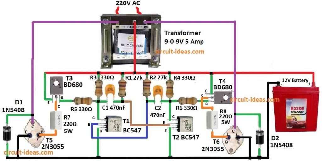
Parts List:
| Components | Values | Quantity |
|---|---|---|
| Resistors | 27k 1/4 watt | 2 |
| 330Ω 1/4 watt | 4 | |
| 220Ω 5 Watt | 2 | |
| Capacitors | Ceramic 470nF | 2 |
| Semiconductors | Transistors BC547 | 2 |
| Transistors 2N3055 | 2 | |
| Transistors BD680 | 2 | |
| Diode 1N5408 | 2 | |
| Transformer 9-0-9V 5 Amp | 1 | |
| Battery 12V | 1 |
Using 50Hz oscillator with transistor astable:
Two small transistors BC547 and some parts like resistors and big capacitors make astable multivibrator; also, this part give 50Hz pulse to start inverter work.
Also, before going to output transistors small signal get bigger by BD680 transistors and these are in Darlington type so they give more current.
Then 2N3055 output transistors take this strong current and work at high level and they push power into transformer windings.
As a result, transformer then give 220V AC from its secondary wire, each side has one 2N3055 transistor which gives 100 watt power.
Also, the signal is 50Hz square wave, input is 12V 5A which is around 90 Watts and output can be 220V or 120V with little changes.
Heatsinks are good for T3, T4, T5 and T6 to keep cool.
Here, capacitor and resistor values decide the frequency which is around 50Hz or 60Hz and this oscillator is simple transistor astable type.
Finally, if required, we can change frequency easy by changing resistor or capacitor on transistor base, which is made to give about 50Hz but we can adjust if needed.
Formulas and Calculations:
Formula to Find Oscillator Frequency:
f = 1 / T = 1 / 1.38RC
where:
- f is frequency of astable multivibrator in hertz Hz
- T is time of one full cycle which is high + low are in seconds
- R is resistance in ohms Ω
- C is capacitance in farads F
- 1.38 is fixed number used in this formula for this type of circuit
This formula says frequency and time constant RC are opposite and if RC goes up frequency goes down and RC is just R multiplied by C.
Example Calculation:
f = 1 / (1.38 × 27000 × 4.7E-7)
= 57.10 Hz
So with these parts the astable multivibrator gives around 57.10 Hz.
Note:
This is just rough value but the real circuit may give little more or less because of:
- Transistors are not perfect
- Real resistors and capacitors have small difference from written value
- Extra small resistances or capacitances are in the circuit
So to get more exact frequency we can check with meter or use circuit simulator.
How to Build:
To build a 220V Inverter Circuit using 2N3055 Transistors follow the below steps foe connections:
- First, put the BC547, BD680 and 2N3055 transistors on PCB same as shown in the diagram.
- Then place the resistors and capacitors by looking at their values and positions in the circuit.
- After that, use the correct resistor values like shown in the parts list.
- Next, connect the transformer wires correctly and follow the design to ensure all winding connections are right.
- Also, transformer details must match the design exactly.
Cooling the Transistors:
- Add heatsinks to T3, T4, T5 and T6 transistors, this helps remove heat and keep them cool during work.
Powering the Circuit:
- Now connect the full circuit to 12V battery or DC power supply and check the power source can give at least 5 Amps.
Testing the Circuit:
- Then turn ON the power and use a frequency meter or oscilloscope to check the output signal.
- Also, if frequency is not close to 50 Hz then change the resistors or capacitors a little bit to adjust.
Connecting Output Load:
- After testing, connect the AC device or other load to the 220V output terminals.
Extra Changes if needed:
- We can fine tune the circuit for better working, also while running, check temperature and output stability.
Safety Tips:
- Be very careful with high voltage and check all wires and parts are connected safely and are not loose.
- Also, follow safety rules while touching or working with electricity and if we are not sure or feel confused take expert help or talk to professional.
Conclusion:
Overall, while building this 220V Inverter Circuit using 2N3055 Transistors always do proper testing, good soldering and take care of each small part.
Lastly, most important keep yourself safe every time while testing or using the inverter.
Leave a Reply