Unlike a standard wall outlet, this AC Power Outlet with Timer Circuit incorporates a built-in timer; as a result, it functions as a timer plug, also known as an outlet timer.
Also, we can plug other device into it.
Furthermore, a small chip called the 555 timer acts as the brain of the circuit, also it generates a square-wave signal by rapidly switching its output ON and OFF.
Speed of wave change by small parts with resistors and capacitor which look like tiny knobs and battery and this speed decide how fast our device turn ON and OFF.
We can also use online calculator to know how long device stays ON and OFF, so this small timer help us set lamp to turn ON at sunset and OFF at sleep.
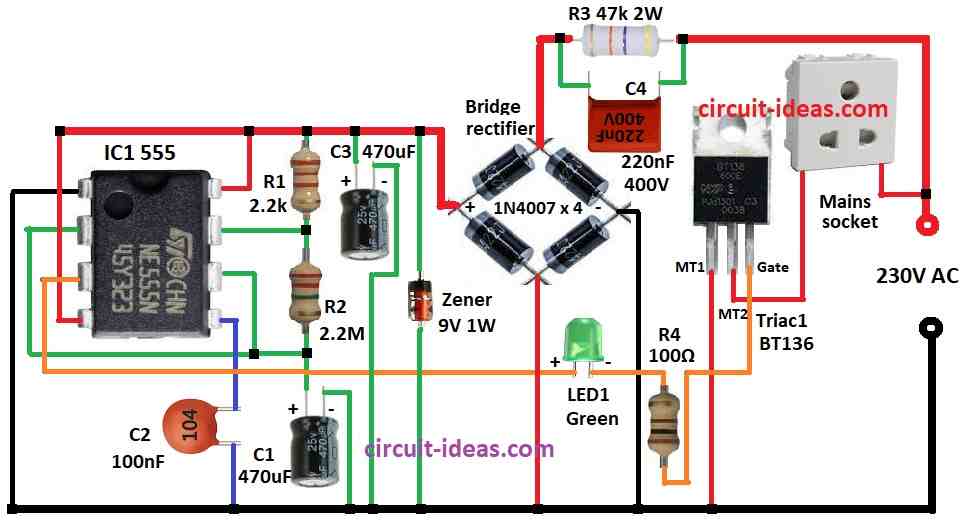
Circuit Working:
Parts List:
| Components | Values | Quantity |
|---|---|---|
| Resistors (All resistors are 1/4 watt unless specified) | 2.2k | 1 |
| 2.2M | 1 | |
| 47k 2W | 1 | |
| 100Ω | 1 | |
| Capacitors | Ceramic 100nF | 1 |
| PPC 220nF 400V | 1 | |
| Electrolytic 470μF 25V | 2 | |
| Semiconductors | IC 555 | 1 |
| Triac BT136 | 1 | |
| LED green 5mm 20mA | 1 | |
| Zener diode 9V 1W | 1 | |
| Bridge rectifier diodes 1N4007 | 4 | |
| Mains socket | 1 |
To begin with, this circuit uses AC power from wall directly and there is no need for step-down transformer.
How it work:
AC Lowering:
Resistor R3 and capacitor C4 together reduce AC voltage, R3 help C4 discharge when power goes OFF and C4 block sudden voltage changes with capacitive reactance.
AC to DC Conversion:
Bridge rectifier change low AC to pulsing DC.
Voltage Control:
Zener diode keep DC voltage steady at about 9V and capacitor C3 remove small ripples before power goes to timer.
Timer Control:
555 timer work in astable mode which is always ON, it make square wave pulses with ON/OFF signals and it changes resistor R2 or capacitor C1 to change ON/OFF time.
Power Switching:
TRIAC BT136 act like switch between neutral and outlet and Gate of TRIAC connect to timer output.
When timer send high pulse then TRIAC turns ON and power goes to outlet and when timer send low pulse then TRIAC turns OFF and outlet stops the power.
Result:
Device plug in timer plug will turn ON/OFF again and again and with current parts it stays ON 23 mins and gets OFF 23 mins; hence, if we only want auto shut-off one time then make timer monostable.
Formula:
To control AC power we can make astable multivibrator circuit using resistors, capacitors, transistors, IC (timer chip) and TRIAC (for AC switching); also this circuit turn AC load ON and OFF again and again.
Simple Circuit Idea:
In diagram R1 and R2 are the resistors and C1 and C2 are the capacitors
Time Formula:
Time for ON and OFF (T) is:
T = 0.693 × (R1 + R2) × C1
This formula shows how quickly the switching circuit controls the ON and OFF times of an AC device.
Furthermore, we can modify the resistor and capacitor values to suit our requirements, but, however, special applications may require additional components.
How to Build:
To build a AC Power Outlet with Timer Circuit follow the below mentioned steps for connections:-
- First, pin 1 of 555 connects to ground
- Next, pin 2 connect to pin 6 and C1 from pin 6 and 2 connects to ground
- Then pin 3 connect to TRIAC gate through R4 and LED1
- Now pin 4 connects to positive supply and pin 8 also connects to positive supply
- After that, pin 5 connects to ground through C2.
- R2 connects between pin 7 and pin 6 and 2 and also R1 connects between pin 7 and positive supply
- Also, C3 connects from positive supply to ground
- Zener Diode of 9V connects between positive and ground.
- C4 and R3 are in series with AC line to drop voltage and bridge rectifier convert low AC to DC
TRIAC1:
- Now MT1 connects ground, MT2 connects one side of AC socket and other side of socket connects to 230V AC and then gate of pin 3 of 555 connects through R4 and LED1
Safety First:
- AC is dangerous we should be careful, if not sure about electronics then ask licensed electrician to help.
- Use parts rated for 230V AC, with wrong parts may burn or catch fire, so always unplug before touching the circuit and also do double check.
- Ground the box properly to avoid shock and do not build this if anyone do not fully understand high voltage risk.
Conclusion:
Overall, with this AC Power Outlet with Timer Circuit we can control AC appliance with timer, as it is smart and useful but safety is most important; so if AC makes us nervous then use safer method or ask professional for help.
Leave a Reply