This project is for Arduino Based Automatic Gate Opening and Closing Circuit.
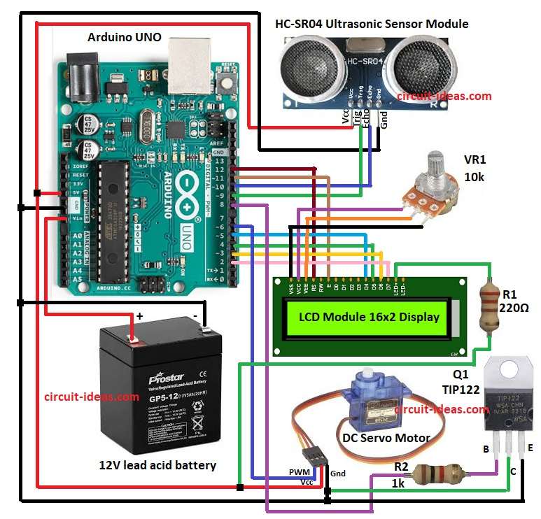
This system uses Arduino UNO, Ultrasonic sensor, NPN transistor, Servo motor, LCD display ,12V battery and few resistors.
When someone comes in front of the gate the ultrasonic sensor detect distance and send signal to Arduino.
Arduino then control motor to open or close the gate.
This system is useful for small automatic door, toy gates model houses and learning automation.
Circuit Coding:
Circuit Coding

#include <LiquidCrystal.h>
LiquidCrystal lcd(12, 11, 5, 4, 3, 2);

const int trigPin = 9;
const int echoPin = 10;
const int motorPin = 8;
long duration;
int distance;

void setup() {
pinMode(trigPin, OUTPUT);
pinMode(echoPin, INPUT);
pinMode(motorPin, OUTPUT);
lcd.begin(16,2);
lcd.print("Gate System Ready");
delay(2000);
lcd.clear();
}

void loop() {
digitalWrite(trigPin, LOW);
delayMicroseconds(2);
digitalWrite(trigPin, HIGH);
delayMicroseconds(10);
digitalWrite(trigPin, LOW);

duration = pulseIn(echoPin, HIGH);
distance = duration * 0.034 / 2;

if(distance < 20) {
digitalWrite(motorPin, HIGH);
lcd.setCursor(0,0);
lcd.print("Gate Opening");
delay(3000);
digitalWrite(motorPin, LOW);
lcd.clear();
lcd.print("Gate Closed");
delay(2000);
}
else {
digitalWrite(motorPin, LOW);
lcd.setCursor(0,0);
lcd.print("Waiting...");
myservo.attach(6);
}
}
Code Explanation:
- First LCD library is added and pins are defined.
- In this design, LCD is started and pins are set.
- In loop ultrasonic sensor measure distance using pulseIn function.
- Distance is calculated with formula distance = (time x speed of sound) / 2.
- If distance is less than 20 cm then motor pin become HIGH so motor run and gate open.
- After delay motor stops and LCD show different messages.
Circuit Working:
Parts List:
| Component | Value | Quantity |
|---|---|---|
| Resistors | 1k 1/4 watt | 1 |
| 220Ω 1/4 watt | 1 | |
| Potentiometer 10k | 1 | |
| Semiconductors | Arduino UNO | 1 |
| LCD Module 16×2 Display | 1 | |
| HC-SR04 Ultrasonic Sensor Module | 1 | |
| DC Servo Motor | 1 | |
| Transistor TIP122 NPN | 1 | |
| Battery 12V lead acid | 1 |
The 12V battery gives power to the DC motor through the TIP122 transistor.
The same battery can also power the Arduino UNO through its Vin pin 7 to 12V input range.
The grounds of Arduino and battery are connected together.
The ultrasonic sensor send ultrasonic sound and receive echo back.
Arduino calculate distance from object.
If distance is less than fixed value like 20 cm then Arduino send HIGH signal to transistor base.
This drive the motor and opens the gate.
After some delay the Arduino stop motor and gate closes.
LCD display show message like “Gate Open” and “Gate Close”.
1k resistor R2 is for pull-up or pull-down resistor which is for current limiting for small signals.
220Ω resistor R1 is for Current limiting for LEDs.
VR1 adjust voltage to an analog input pin 0 to 5V and it control brightness, motor speed or servo position.
Formulas:
Below is the formula for Arduino Based Automatic Gate Opening and Closing Circuit.
Formula for distance: distance = (time * speed of sound) / 2
Speed of sound in air = 0.034 cm per microsecond.
Example: if echo time = 1200 microseconds
distance = 1200 * 0.034 / 2 = 20.4 cm
So Arduino decide if object is closer than 20 cm.
How to Build:
To build a Arduino Based Automatic Gate Opening and Closing Circuit follow the below steps for connections:
- Collect all parts as shown in circuit diagram.
- Connect ultrasonic sensor like VCC to 5V of Arduino, GND to GND of Arduino, Trig to pin 9 and Echo to pin 10.
- Connect LCD display to Arduino pins like RS to pin 12, EN to pin 11, D4 to pin 5, D5 to pin 4, D6 to pin 3, D7 to pin 2.
- Potentiometer first pin connect to VCC (+5V), Middle pin to VEE(contrast) of LCD and Third pin to VSS pin on LCD.
- Servo Motor Red pins connects to 5V of Arduino, Brown/Black pin connects to GND of Arduino and Orange/Yellow pin to Arduino pin 6.
- Emitter of transistor goes to GND and base of transistor go to Arduino pin D8 with 1k resistor.
- Battery positive goes to servo motor positive and battery negative go to transistor emitter and Arduino GND.
- And transistor collector go to motor negative.
- One side of 220Ω resistor go to Arduino +5V and other side go to LCD LED+.
Conclusion:
This article shows how to build Arduino Based Automatic Gate Opening and Closing Circuit.
It uses distance measurement to control motor.
Gate open and close happen automatically.
LCD display make system easy to use.
Project can improve with motor driver IC, limit switch or remote control.
Leave a Reply